Schutz vor Brand durch Erdschluss
Den aktuell effektivsten elektr. Brandschutz stellt die neueste Generation an Schutzgeräten dar, die Fehlerlichtbogen-Schutzeinrichtung (AFDD), diese Schutzeinrichtung wird bereits Normativ nach VDE 0100-420, in den folgenden Anlagen, für einphasige Endstromkreise ≤ 16A gefordert in:
- Schlaf- und Aufenthaltsräumen von Heimen oder Kindertagesstätten, Seniorenheimen und in barrierefreien Wohnungen nach DIN 18040-2
- Gebäude und Räumlichkeiten aus/mit brennbaren Baustoffen
- Gebäude und Räumlichkeiten für unersetzbare Güter
Mehr Informationen zu der neuen Schutzeinrichtung finden Sie im Abschnitt Schutz gegen thermische Auswirkungen (AFDD)
Für alle anderen Bereiche stellt weiterhin ein RCD ≤ 300mA durch die Erkennung von Isolationsfehlern, einen effektiven Brandschutz dar, wie im folgenden Abschnitt beschrieben.
RCDs sind sehr wirksame Geräte zum Schutz vor Brandgefahr [1] aufgrund von Isolationsfehlern, da sie Leckströme (z.B. 300 mA) erkennen können, die für die anderen Schutzmaßnahmen zu niedrig sind, aber ausreichen, um einen Brand zu verursachen.
Die große Mehrheit der elektrischen Kurzschlüsse in Niederspannungsinstallationen sind Isolationsfehler zwischen Leitung und Erde.
Die im vorherigen Abschnitt dieses Kapitels vorgestellten Schutzmaßnahmen gegen elektrischen Schlag gewährleisten eine automatische Trennung der Versorgung im Falle eines Fehlers zwischen einem Außenleiter und einem zugänglichen leitfähigen Teil, der zu gefährlichen Berührungsspannungen führen könnte.
Es kann jedoch auch zu einem Fehler zwischen einem Außenleiter und Erde mit einer niedrigeren Amplitude als dem Schwellenwert des Kabelüberstromschutzes (und ohne Risiko eines „indirekten Kontakts“) kommen (siehe Abbildung F73).
Schutz durch RCDs
An insulation failure between line conductor and earth in dusty and humid environment for instance can lead to an arc fault of low intensity according to line conductor withstand, but high enough to start a fire. Some tests have shown that even a fault current as low as 300 mA can induce a real risk of fire (see Abbildung F74)
This type of fault current is too low to be detected by the overcurrent protection.
For TT, IT and TN-S systems the use of 300 mA sensitivity RCDs provides a good protection against fire risk due to this type of fault. (see Abbildung F75)
The IEC 60364-4-42:2010 (clause 422.3.9) makes it mandatory to install RCDs of sensitivity ≤ 300 mA in high fire-risk locations (locations with risks of fire due to the nature of processed or stored materials - BE2 condition described in Table 51A of IEC 60364-5-51:2005). TN-C arrangement is also excluded and TN-S must be adopted.
In locations where RCDs are not mandatory as per the IEC, it is still strongly recommended that you consider the use of RCDs, bearing in mind the potential consequences of fire.
See Residual Current Devices (RCDs) for the selection of RCDs.
Another solution is to use ground fault protection (see below) but the range of fault current detected will be reduced.
Protection with “Ground fault protection”
In TN-C system, RCD protection cannot be used, as the measurement of earth fault current by a sensor around line conductors and PEN will lead to permanent wrong measurement and unwanted trip. But a protection less sensitive than RCD but more sensitive than conductors’ overcurrent protection can be proposed. In North America this protection is commonly used and known as “Ground Fault Protection”.
Different types of ground fault protections (GFP)
(see Abbildung F78)
Three types of GFP may be used, depending on the measuring device installed:
“Residual Sensing” RS
The “insulation fault” current is calculated using the vectorial sum of currents of current transformers secondaries. The current transformer on the neutral conductor is often outside the circuit breaker.

“Source Ground Return” SGR
The “insulation fault current“ is measured in the neutral – earth link of the LV transformer. The current transformer is outside the circuit breaker.
“Zero Sequence“ ZS (Equivalent to IEC RCD in principle)
The “insulation fault“ is directly measured at the secondary of the current transformer using the sum of currents in live conductors. This type of GFPis only used with low fault current values.
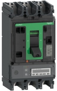
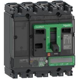
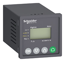
Ground fault protection can be included in the circuit breaker (see Abbildung F77) or performed by a standalone relay. In all cases the device operated by the GFP shall have the breaking capacity of the maximum fault current at the point of installation, alone or in coordination with another overcurrent protective device.
Earth fault monitoring
Increasing the sensitivity of protection system will reduce the risk of fire but can also increase the risk of unexpected tripping on disturbance that are not real fault. (See Sensitivity of RCDs to disturbances). Where balance between sensitivity and continuity of service is challenging, the monitoring of earth fault with no automatic disconnection brings also benefits.
Earth current monitoring and alarming allow:
- Early detection of deterioration of insulation
- Abnormal leakage currents
- Detection of neutral to earth unwanted contact in other place than the dedicated earthing link

Anmerkung
- ^ For more information about electrical fire origins, and the latest solutions to mitigate the risks, download the Electrical Fire Prevention Guide (PDF)
de:Schutz gegen elektrischen Schlag
Schutz mit RCDs
Schaltgeräte mit Fehlerstromschutz gewährleisten, aufgrund der Erkennung von Isolationsfehlern, einen sehr effektiven Schutz in feuergefährdeten Betriebsstätten. Der hier auftretende Fehlerstrom ist für eine Erfassung durch andere Schutzgeräte zu niedrig (Überstrom, Auslösezeit).
In TN-S, TT- und IT-Systemen können Fehlerströme auftreten. Schaltgeräte mit Fehlerstromschutzeinrichtung mit einer Empfindlichkeit von 300 mA gewährleisten einen Schutz aufgrund dieser Fehlerströme in feuergefährdeten Betriebsstätten. Untersuchungen haben ergeben, dass die durch Feuer entstehenden Kosten pro Schadensereignis in Industrie- und Dienstleistungsgebäuden sehr hoch sein können.
Analysen haben gezeigt, dass das Brandrisiko, hervorgerufen durch die Überhitzung elektrischer Betriebsmittel, eng mit der durch eine fehlerhafte Koordination zwischen den maximalen Bemessungsströmen der Leitungen (oder isolierter Leiter) und den Einstellungen der Überstromschutzeinrichtungen zusammenhängt.
Ebenso kann es durch Veränderungen des Anlagenaufbaus (Hinzufügen von Kabeln/ Leitungen auf ein bereits genutztes Kabelträgersystem) zu einer Überhitzung kommen.
Durch diese Überhitzung kann ein Isolationsfehler in den elektrischen Betriebsmitteln entstehen, der sich zu einem elektrischen Lichtbogen ausbilden kann. Diese elektrischen Lichtbögen entwickeln sich, wenn die Fehlerschleifenimpedanz größer als 0,6 Ω ist und treten nur bei einem Isolationsfehler auf. Tests haben ergeben, dass sich das Brandrisiko bei einem Fehlerstrom von mehr als 300 mA stark erhöht (siehe Abb. F26).


